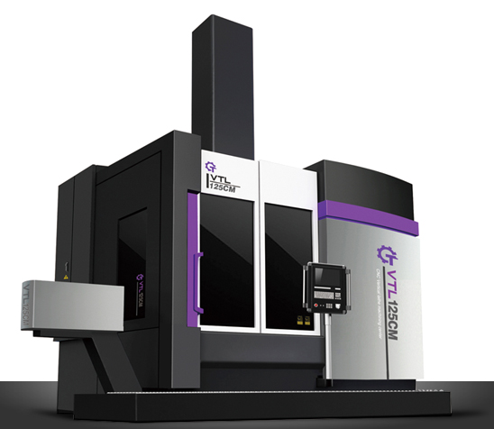
Must see! Composition structure of large vertical lathe |
| Time: 2021-01-25 View: 2269 Burst: |
|
Large vertical lathes are widely used in industries such as heavy machinery manufacturing, mining equipment manufacturing, steel industry, chemical equipment manufacturing, power equipment manufacturing, railway locomotive and vehicle manufacturing, and metallurgical machinery manufacturing.
The machine tool consists of a frame consisting of left and right columns, a top beam, and a worktable base to withstand the load during cutting. The crossbeam moves up and down along the column guide rail, and the crossbeam lifting motor and worm gearbox are placed on the top beam. The crossbeam is clamped on the column by a disc spring through a lever, and the operation button for lifting the crossbeam is located on the hanging button station. The gearbox is fastened to the rear of the workbench base, and the main motor is connected to the gearbox through an elastic coupling. The gearbox is driven by a variable speed cylinder to exchange gears and achieve sixteen different speeds. The speed change switch is located on the hanging button station. The worktable is directly started and braked by the main motor through the gearbox. The worktable only rolls in the forward direction, but can be operated in both forward and reverse directions for easy alignment during work. The workbench is equipped with wear-resistant guide plates made of zinc aluminum copper alloy, and pressure oil (2-4 kg/cm2) is introduced between the guide rails to improve their load-bearing capacity. Two 3182100 double row short cylindrical roller bearings are installed on the worktable spindle, with tapered holes in the inner ring to adjust the radial clearance, ensuring that the spindle can work smoothly with high precision. The start, brake, and jog buttons for the workbench are located on the hanging button station. The two feed boxes on the left and right sides of the large vertical lathe are installed at both ends of the crossbeam. The structure of the two feed boxes is the same. At the rear of the feed box, there is a tool holder feed motor and a fast moving motor, and the working feed is achieved by changing gears to achieve eighteen different feed rates. The operating handle for changing the feed rate is located in front of the feed box, which is equipped with an electromagnetic clutch to select the direction of the tool holder's working feed or rapid movement. The direction selection switch and feed for the tool holder movement, as well as the quick movement operation button, are located on the hanging button station.
|


